2026-10-31 · 19 min · 3d · computer-vision · depth-estimation · geometry · point-cloud

Why read this
Hightop 30%No code or weights yet, so I rebuilt the three-stage ray fit on four analytic cameras and measured the ray error of the project page's own point clouds.
- Interactive explanations
- Original analysis
- A lasting reference
3D & spatialNothing to runPractitioner paper
How this was scored
- Is it new?
- 2 of 3: A real new idea, method or capability
- Can I trust it?
- 2 of 3: Measures key facts from files, code or configs
- Can I run it?
- 1 of 3: API-only, gated or restrictive licence
- Will I understand it?
- 3 of 3: Mechanism carried by interactives built from real code or data
- Can I act on it?
- 2 of 3: A concrete recipe, numbers or comparison
- Will it last?
- 2 of 3: A reference for a year or more
- Does it affect many?
- 1 of 3: A specialist community
- Only here?
- 2 of 3: A teardown or measurement few others did
Score 67 of 100, ranked 199 of 666 rated articles. Each question is answered 0–3 by hand, and a 3 is rare. How articles are scored
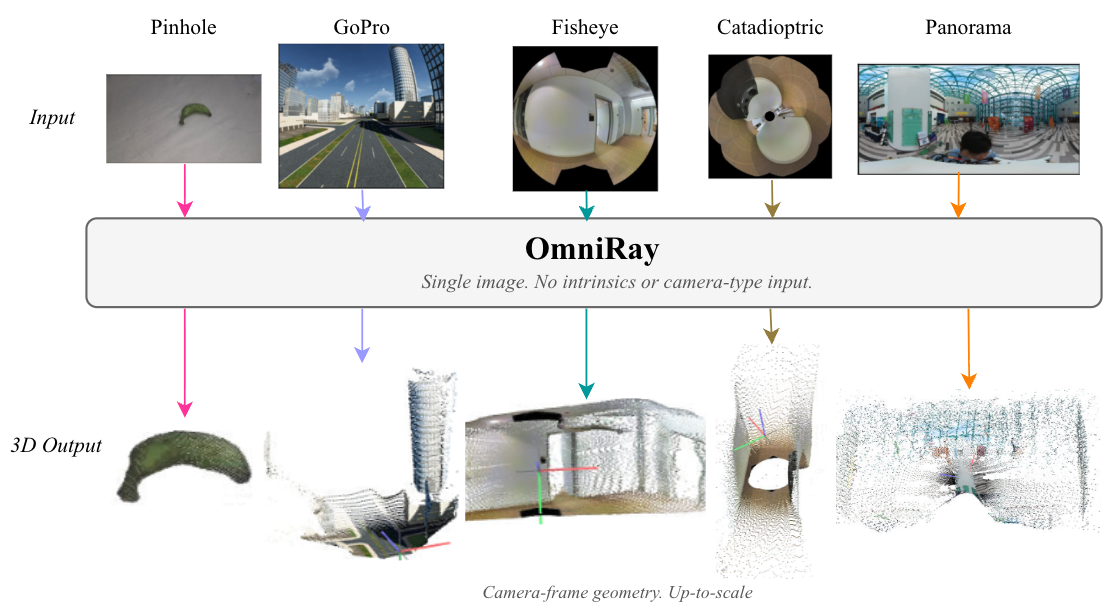
A single photograph from a phone, a GoPro, a fisheye or a 360° panorama, no calibration file, and a point cloud comes out. That is the claim of OmniRay, a paper from Johns Hopkins and Virginia posted on 22 October 2026 (arXiv 2610.31645, CC BY 4.0). I read the paper in full and the repository its project page links, and I need to say first what is and is not there. The paper is there. The repository is the project page's source: its README says "Code and models are planned to be open-sourced upon publication", the page itself says Code and models: TBD, and the Hugging Face checkpoint the page links to does not exist. Nothing here can be run, so this article checks the parts that can be checked by other means (measured means I computed it, reported means it is the paper's number, reasoned means it is my inference).
I did three things beyond reading. I rebuilt the paper's three-stage ray representation at toy scale and fitted it to analytic ground-truth rays of four cameras. I spoiled a fisheye in two controlled ways and watched which stage absorbs which deviation. And I measured the ray error of the point clouds the project page does ship, five benchmark examples with ground truth and two baselines, because those files make a per-pixel comparison possible. GOFish, a fisheye Gaussian-splatting paper from the same week, attacks the neighbouring problem from the other side: it is given a camera model and has to render across the whole field of view; OmniRay is given nothing and has to find the camera.
A camera is a map from pixels to rays
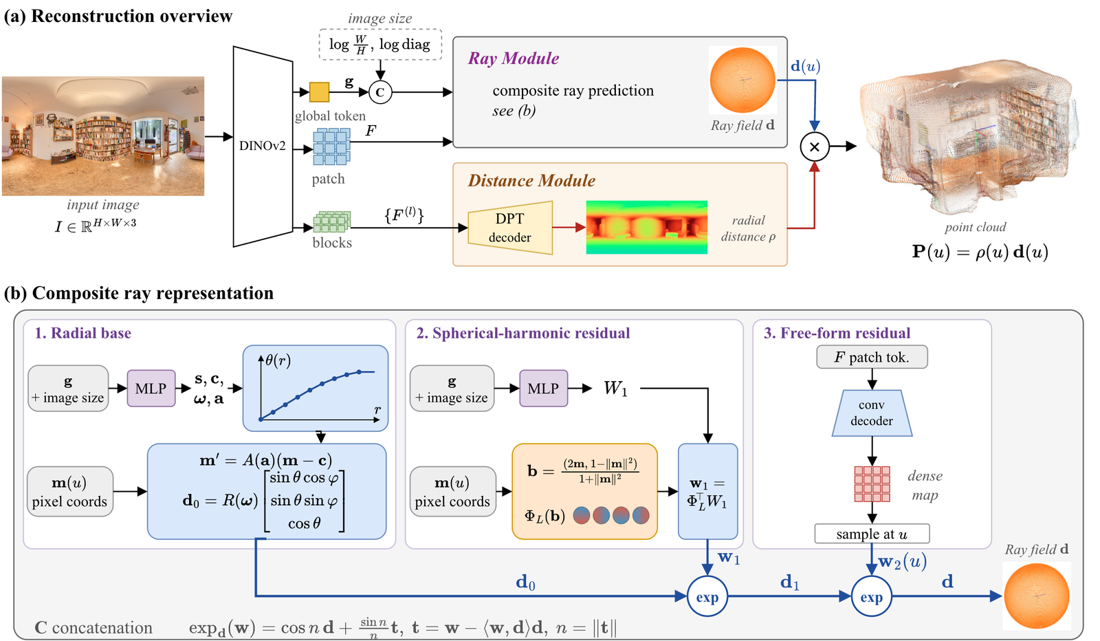
Take any camera whose rays all pass through one point, which is what "central" means. Each pixel then looks along one direction, a unit vector d on the sphere. A 3D point is that direction times a distance, P = ρ·d. The direction depends only on the camera. The distance depends only on the scene. OmniRay is two networks that share one encoder: a Ray Module that predicts d for every pixel, and a Distance Module that predicts ρ (reported).
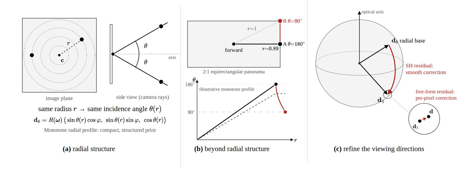
A pinhole camera maps a pixel at distance r from the image centre to the angle θ = atan(r/f) from the optical axis. Two things go wrong when you use that as the only mental model. First, a pinhole cannot see at or beyond 90° from its axis, because the image plane would have to be infinitely large, so a fisheye image cannot be undistorted into one pinhole view without cropping or stretching its edges (reported, the paper's argument). Second, a model trained mostly on pinhole data has no reason to expect that pixels at the edge of an image look more than about 45° off-axis, and on a 180° fisheye they look 90° off-axis (reasoned).
The plot is the whole idea of the paper's first stage. For the pinhole, the fisheye and the mirror camera, every pixel lands on a single curve θ(r): same distance from the centre, same angle from the axis. A monotone function of r, with a few parameters, describes all three. For a 2:1 equirectangular panorama the points fill an area. In the paper's Figure 3b, point A on the midline at the image's right edge is closer to the centre than point B in the corner, yet A looks straight backwards (180°) and B looks sideways (90°). No function of r can put both right. I computed how wrong: on my sampling, with 24 radius bins and a straight line fitted inside each bin, the best any θ(r) can do on the panorama leaves an RMS gap of about 13°, while for the pinhole, the fisheye and the mirror camera it leaves 0.004°, 0.000° and 0.05° (measured, the number under the plot).
The ray field as three rotations
OmniRay builds the ray field in three steps, and each step is a rotation on the sphere (reported; the equations are the paper's, the reading is mine).
Stage 1, the monotone radial base. A small network turns a global image token into 24 numbers: sixteen non-negative increments for a piecewise-linear profile θ(r) over r in [0, 1.3] (the image's half-diagonals), a principal-point offset, an axis-angle rotation, and three numbers for an upper-triangular map that handles anisotropic scaling and shear. The increments pass through a softplus and are summed into knot heights, so θ can only rise as r grows. The base ray is the usual polar form, d₀ = R(ω)·[sin θ cos φ, sin θ sin φ, cos θ]. Nothing caps θ at 90°, so the base already covers lenses that see past the equator. Because the profile is evaluated directly, no parametric projection model has to be inverted.
Stage 2, a spherical-harmonic residual. The same network predicts a single matrix of 192 coefficients (3 × 64, for harmonics up to degree 7) shared by every pixel of the image. Each pixel is lifted onto the sphere by an inverse stereographic projection, evaluates the 64 basis functions there, and gets a 3-vector w₁. Only the part of w₁ that is tangent to the current ray matters, and its length is the rotation angle: the ray moves that far along the great circle in that direction, d₁ = exp over d₀ of w₁. A smooth correction with 192 numbers can rotate rays by a lot where the radial profile is wrong across the image.
Stage 3, a free-form residual. A small convolutional decoder over DINOv2's dense feature map predicts one more tangent vector per pixel, applied the same way: d = exp over d₁ of w₂. It is limited by the resolution of the feature map, and it is for what is left: local deviations a global basis cannot reach.
Both residual heads start at zero, so the composition starts as the radial base, and the lengths of the two tangent vectors are the rotation angles each stage applies, which is a built-in measure of how far a camera departs from the representation beneath it. There is no model selection and no camera-type label: the same three stages handle a pinhole, where the residuals stay near zero, and a panorama, where they do most of the work.
The paper's own illustration of why the stages are layered is worth reading closely.
What the distance module and the loss add
The Distance Module is a DPT decoder over four intermediate encoder blocks. It predicts the radial distance ρ rather than perpendicular depth Z, because ρ = Z / d_z and d_z goes to zero as a ray nears 90° and changes sign beyond it; ρ stays defined across any field of view (reported).
Training supervises the final ray field and both intermediate ones with an angular loss, so a correct final ray cannot be reached through an arbitrary base, and weights the error most at the image's outer ring, where it concentrates. A point-cloud loss divides each cloud by its own mean point norm, which removes the scale a single image cannot determine. The encoder is DINOv2 ViT-L/14; the Ray Module is trained alone first, with its three components switched on in order, then end to end on 8 A40 GPUs (reported).
How the paper keeps it from memorising its cameras
The training data are panoramas from 2D3DS (indoor offices, areas 1 to 4) and 360Loc (the Atrium and Piatrium scenes), rendered as perspective, fisheye and panoramic views. The trick that matters is random-lens augmentation: each training image goes through a randomly sampled central camera, defined by a viewing direction, a monotone radial profile drawn from positive spline increments, and an imaged region that may be a rectangle, a circle or an annulus. Two camera types are removed from training completely: a GoPro fisheye, and a Nayar catadioptric camera, a paraboloid mirror that images an annulus from 40° to 155° about its axis. Draws near either are rejected (reported).
Without the augmentation, the model stays strong on cameras it saw, but its held-out catadioptric error rises from 1.1° to 30.9° and the GoPro error from 5.5° to 8.0° (reported, Table 2). The augmentation is not a detail of the recipe; it is what makes the representation transfer.
What the paper reports
Three tables carry the claims; I keep the numbers as printed (reported).
The oracle test (Table 1) fits each representation directly to ground-truth rays, before any network exists. A 6-parameter pinhole gets 5.7° on a fisheye and about 50° on a panorama and a mirror camera. A 16-knot radial profile reaches 0.002° on the fisheye and 0.104° on the mirror camera but stays at 22.8° on the panorama, however many knots it has. A degree-7 SH field gets 0.276°, 0.641° and 0.295° on the three; radial plus an SH residual, 216 parameters, is under 0.25° on all three.
The benchmark (Table 2) gives mean ray error and relative Chamfer distance. On seen cameras OmniRay gets 0.140° and 0.0179, against 6.336° and 0.0760 for UniK3D and 33.028° and 0.1999 for Depth Anything 3. On the withheld catadioptric camera both baselines are above 75° and OmniRay is at 1.120°; on the withheld GoPro the margin is slim, 5.533° against UniK3D's 6.342°; on the unseen street dataset PanoCity it is 1.350° against 21.220° and 50.533°. On CO3Dv2, object-centric pinhole photos, OmniRay's 2.967° is not the best: Depth Anything 3 gets 2.041° and UniK3D 2.676°.
The ablation (Table 3) trains only the Ray Module. The radial base alone gives 21.8° on panoramas and a free-form field alone 11.3° on the withheld mirror camera. Radial plus SH plus free-form, trained in stages, gets 0.399° on panoramas, 1.322° on fisheye and 1.538° on the mirror camera, and beats both jointly trained three-term versions on all five configurations.
The paper's one stated limitation: the model was trained on ground-level panoramas with the horizon near the middle, and on an aerial panorama with the horizon near the top, the predicted rays cover only a bounded, forward-facing region. The authors read it as a dependence on the distribution of viewing altitudes.
A toy version of the oracle test
I rebuilt the three stages at toy scale and fitted them to analytic ground-truth rays, which is the paper's Section 4.1 procedure applied to cameras I could write down. This is my re-implementation of the idea in numpy and torch on a CPU, not the authors' code, and a different optimiser and camera sampling, so compare the shape of the results, not the digits.
The cameras are a 90° pinhole, a 180° equidistant fisheye, the Nayar mirror (40° to 155°), and a 2:1 equirectangular panorama, each on a small pixel grid. Stage 1 is the 24-parameter monotone radial base, with the principal point, rotation and anisotropy, fitted by L-BFGS with several starts. Stage 2 adds a degree-7 SH residual (192 coefficients, with a real spherical-harmonic basis I wrote by recurrence and checked for orthonormality: the Gram matrix of 200,000 random points is the identity to 0.009). Stage 3 adds a free-form residual on a coarse grid, a stand-in for the convolutional decoder. Each stage is fitted with the earlier ones frozen, as in the paper's staged training. I also fit a pinhole and a spherical-harmonic field alone, as the paper's table does.
The picture matches the paper's argument on every point it can. A pinhole model is wrong on any camera that sees past 90° (9.1° on the fisheye, 40.1° on the panorama, 49.6° on the mirror). The radial base is nearly exact on the three lens-like cameras, 0.022° on the pinhole, 0.001° on the fisheye and 0.043° on the mirror camera, and it fails on the panorama at 31.5°. The paper reports 22.8° for the same case. Both numbers are upper bounds on the ceiling, and mine comes from a weaker search, so the honest reading is "tens of degrees, not a fraction". Stage 2 is what removes that ceiling, taking the panorama from 31.5° to 0.75°, and stage 3 takes it to 0.059°.
Two results do not match the paper's ordering, and I would rather say so than smooth them over. On the panorama, a spherical-harmonic field fitted alone (0.04°) beats my staged radial-plus-SH fit (0.75°). The reason is the optimiser, not the representation: the SH-alone fit is a linear least-squares problem solved exactly, while the staged fit is non-convex and starts from a base that is 31° off. The paper's composite beats its SH row (0.217° against 0.641°) with a trained network and a larger budget. And on the fisheye my SH-only fit is essentially exact, 0.000003°, where the paper has 0.276°, because mine is the least-squares optimum on a smooth cap of the sphere and theirs is a budget-limited fit including a rotation. Neither changes the conclusion the table is for. It does show that "the SH field alone is enough" and "the radial base is enough" are both statements about a camera and an optimiser, which is the paper's case for having both.
How much each stage absorbs
The oracle table says what each stage can express. It does not say what each stage is for, so I spoiled a fisheye in two ways and fitted the stages in order. The base is the 180° equidistant fisheye from above. The smooth spoiling adds a random tangent deviation built from spherical harmonics of degree 1 to 3, scaled to a stated RMS in degrees. The local spoiling adds six Gaussian bumps, each about 2.7 pixels wide on a 64-pixel image, with a stated peak size. Every point is the mean of five random draws. I report the mean angular error and the share of pixels whose ray is still more than 0.25° off.
Smooth deviations are the radial base's problem and the SH residual's solution. The radial base is left with an error of about half the deviation: 0.26° for a 0.5° deviation, 1.03° for 2°, 4.05° for 8°. At 0.5° it already leaves 49% of pixels beyond 0.25°, and at 1° it leaves 85% (measured). The SH residual removes almost all of it, to 0.004° at 0.5°, 0.016° at 2° and 0.041° at 8°, about one percent of the deviation, with at most 0.2% of pixels still beyond the threshold. This is the least informative result here, and I want to say why. The deviation I added is built from the same kind of function the SH residual fits, so absorbing it is close to what that stage is designed to do. What the table does show is how little room a radial profile has: a half-degree smooth deviation, the size of an ordinary lens imperfection, already puts half the rays out of tolerance.
Local bumps are the real test, because a degree-7 basis cannot represent a feature 2.7 pixels wide. The radial base leaves a mean error of about 0.11 times the bump's peak. The SH residual helps only a little: at 8° bumps the mean falls from 0.913° to 0.694° and the share of pixels beyond 0.25° barely moves, from 75.2% to 72.2%. At 2° the share even rises, from 14.8% to 18.2%, while the mean falls, because a global correction fitted to local bumps moves some error onto pixels that had none (reasoned). The free-form stage is the one that works: 0.139° at 8° and 0.036° at 2°, with the share beyond 0.25° down to 14.9% and 1.8%. The share of pixels still wrong after stage 2 is the share that a per-pixel residual has to touch, and it grows quickly with the deviation: 1.7%, 5.8%, 18%, 43% and 72% for bumps of 0.5°, 1°, 2°, 4° and 8°.
That is the paper's case for three stages in numbers I can reproduce: a smooth global correction and a local one are different jobs, and a representation with only one of them is the wrong shape for half the lenses. Limits of the toy: my free-form stage is a 16 × 16 grid with 4-pixel spacing, fitted by L-BFGS with the earlier stages frozen, not a convolutional decoder trained end to end; the bumps are Gaussians I chose; and a real lens has structure I did not model. I did not test the paper's claim that staged training beats joint training.
The point clouds on the project page
The repository does ship something concrete: for five benchmark examples, one per camera type, it holds the input image and four point clouds of 40,000 points each (13,001 for the object-centric pinhole example): the ground truth, OmniRay, UniK3D and Depth Anything 3. The README says they are sampled at the same pixels, and I checked that the vertex colours agree in all four files of each example. So vertex i is one pixel in every cloud, the ray of pixel i is the unit vector of point i, and the angle to the ground-truth ray is exact per pixel.
I wrote the metrics from the paper's definitions (script and results are in the article's code folder) and ran them on all five. These are single images chosen by the authors for their page, not the paper's test sets. Treat them as a spot check, with the paper's own macro-averages marked beside each bar.
On the fisheye and panorama examples OmniRay's mean ray error is 0.04° and 0.28°, against 6.7° and 21.9° for UniK3D and 32.7° and 64.7° for Depth Anything 3 (measured). On the withheld mirror camera OmniRay is at 4.4° and both baselines at about 125°. The baselines' 125° is a different kind of failure from a distortion: it is what you get when the rays point into the wrong part of the sphere, which is what a model that assumes the image centre looks forward does with an image whose centre is the sky and whose rim is the ground (reasoned). On the withheld GoPro the example gives 3.2° against 7.8° and 17.0°. On the pinhole example OmniRay's ray error is 0.27° against UniK3D's 0.46°, but UniK3D's relative Chamfer distance is slightly better, 0.0034 against 0.0040, which fits the paper's CO3Dv2 numbers, where OmniRay is not ahead.
The point-cloud metric follows the paper's procedure: each prediction is scaled to the ground truth by the ratio of median radial distances, and accuracy and completeness are median nearest-neighbour distances divided by the scene's mean point norm. Some things I did not do. I did not re-render anything and I do not know how the authors chose these examples. The OmniRay clouds already sit at the ground truth's scale (the median-alignment factor is within 3% of 1 for all five), which says they were aligned before export, but I cannot see how. And one image per camera says nothing about variance. The paper's macro-averages for OmniRay on the same cameras are 0.154°, 0.110°, 1.120° and 5.533° for the fisheye, panorama, mirror and GoPro, so these examples are better than the averages for the fisheye (0.04°) and the GoPro (3.2°) and worse for the panorama (0.28°) and the mirror camera (4.4°). One image per camera is too few to say more.
What this does and does not settle
Four things hold up. The representation does what the paper argues: a radial profile is nearly exact for lenses and cannot express a panorama, an SH residual removes that ceiling, and a per-pixel residual finishes the job (my toy, in the same order as the oracle table). The composition is cheap: 24 numbers for the base and 192 per image for the SH residual. Random-lens augmentation is a large part of the result. And on the authors' own example clouds the rays are as accurate as the paper's averages say.
Several things are open. There is no code and no checkpoint, so nobody outside the authors can try a lens of their own, and the live demo shows chosen images, not an interface for new ones; "no intrinsics at inference" cannot be tested. The withheld-GoPro result is the weak one, and on object-centric pinhole photos OmniRay is not the best. The aerial-panorama failure suggests the model has learned something about how panoramas are usually taken. I do not know the model's size, its speed, or the free-form decoder's resolution, because the paper does not say.
The practical reading is narrower than the headline. If you shoot fisheye or panoramic footage and need a per-pixel ray field without a calibration step, this is a representation the paper shows working across lens types in one forward pass, and the release is worth watching for. Until then, the check that carries over to any ray representation is the one above: fit it to the rays of the lens you care about and see which stage absorbs the deviation.
Sources
- Guruprasad, Yadav, Peng, Chellappa and Bhattad, OmniRay: Camera-Agnostic Monocular 3D Reconstruction with Composite Ray Fields, arXiv 2610.31645v1, 22 October 2026 (CC BY 4.0). Figures 2 and 3 above are from the paper.
- OmniRay project page and its GitHub repository (the project page's source at commit de2f236, 28 October 2026; no licence file; "Code and models are planned to be open-sourced upon publication"). The Hugging Face checkpoint it links,
gnam8991/omniray, returns an error on 31 October 2026. - Piccinelli et al., UniK3D, and Lin et al., Depth Anything 3, as cited by the paper for the baselines.
- Our scripts and outputs, committed with this article under
public/articles/omniray/code/:ray_oracle.pyandoracle_results.json(the toy fits),demo_metrics.pyanddemo_metrics.json(the project-page clouds), andgen_data.py(which turns both into the widgets' data).
Related reading on this site: Gaussian-splat capture in practice covers the 360° cameras and fisheye footage that models like this are meant to read.