2026-06-28 · 9 min · state-estimation · kalman-filter · slam · robotics
Why read this
Notabletop 60%The Kalman filter as fusing two Gaussians, with a live tracker, runnable NumPy and the path to EKF, iEKF and the error-state filter used in LIO.
- Runs on a laptop CPU
- Interactive explanations
- Evergreen reference
Robotics & embodiedPractitioner guide
How this was scored
- Is it new?
- 0 of 3: Repackaging or news of a known thing
- Can I trust it?
- 1 of 3: Spot-checks a few numbers
- Can I run it?
- 3 of 3: Open, permissive, runs on reader hardware with instructions
- Will I understand it?
- 3 of 3: Mechanism carried by interactives built from real code or data
- Can I act on it?
- 2 of 3: A concrete recipe, numbers or comparison
- Will it last?
- 3 of 3: Evergreen fundamentals
- Does it affect many?
- 2 of 3: A widely used model, tool or lab release
- Only here?
- 1 of 3: Some original analysis
Score 61 of 100, ranked 235 of 454 rated articles. Each question is answered 0–3 by hand, and a 3 is rare. How articles are scored
I spend a lot of time on odometry and SLAM, and underneath almost all of it is the same idea: you have a noisy sensor, and a model of how the thing you're tracking moves, and you want to fuse them into a single best estimate that also tells you how much to trust itself. That's the Kalman filter. It's the optimal recursive estimator for a linear system with Gaussian noise, and once it clicks, you see it everywhere — GPS, IMUs, radar tracking, and the LiDAR-inertial filters I'll build on in the next article.
Let me derive it the way it actually makes sense: as fusing two Gaussians.
Two sources of information
You're tracking a state — say the position and velocity of something. You have two things:
- A process model: how the state evolves on its own. For constant velocity, . You can predict forward, but the prediction drifts — it accumulates uncertainty.
- A measurement model: a sensor that observes some function of the state, noisily. A position sensor gives you .
Neither is enough alone. The prediction drifts; the sensor is noisy and jittery. The Kalman filter combines them, and the key fact is that combining two Gaussian estimates yields a third Gaussian that is sharper than either input.
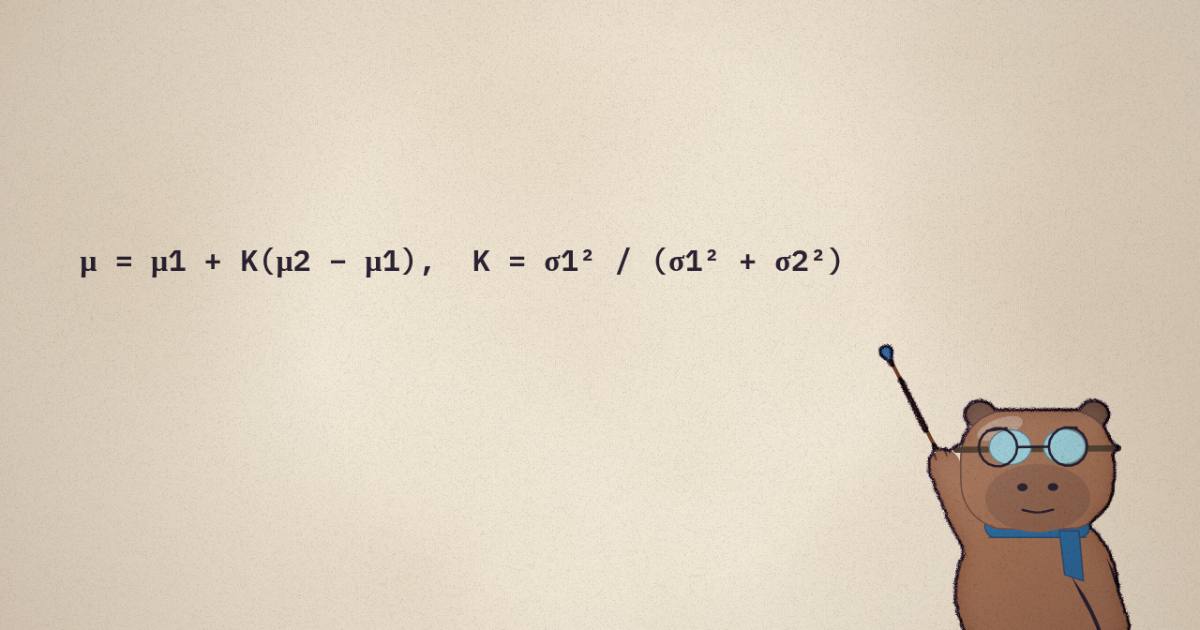
The posterior mean is μpred + K(z − μpred): the gain K = σ²pred / (σ²pred + σ²z) is the fraction of the way you move from the prediction toward the measurement. Shrink the sensor noise and K → 1 (snap to the measurement); shrink the prediction noise and K → 0 (keep the prediction). Either way the posterior is narrower than both inputs — combining two noisy estimates always tells you more than either alone. That’s the whole filter.
That's the whole update step. If the prediction is and the measurement is , their normalized product has
is the Kalman gain — the fraction of the way you move from the prediction toward the measurement, set by which one is more certain. Trust the sensor () and ; trust the prediction () and . Everything else is this, generalized to vectors.
The predict-update cycle
In general the state is a vector with covariance , and the models are linear maps with Gaussian noise:
is the state-transition, maps state to measurement, is process noise (how much the model drifts), is measurement noise. The filter alternates two steps forever:
Predict — push the state and its uncertainty forward through the model:
Update — correct with the measurement, by the matrix Kalman gain:
Watch it run on a constant-velocity tracker. The state is , the sensor sees only position, and the filter has to infer velocity and smooth the noise. Drag and to feel the trust trade-off the gain encodes:
Raise R and the filter trusts its prediction over the sensor — the estimate smooths out but lags. Raise Q and it trusts fresh measurements more — it snaps to the data but gets jittery. The Kalman gain is exactly this ratio, computed optimally each step from the covariances, and the band is the filter’s own honest estimate of how unsure it is.
In code
The whole thing is a few lines of linear algebra. Here's the constant-velocity tracker above, in NumPy — no framework, runnable as-is:
import numpy as np

dt = 1.0
F = np.array([[1, dt],      # constant-velocity transition
              [0, 1]])
H = np.array([[1.0, 0.0]])  # observe position only
Q = 0.5 * np.array([[dt**3/3, dt**2/2],   # process noise (drift)
                    [dt**2/2, dt]])
R = np.array([[49.0]])      # measurement noise (sensor variance)

x = np.array([[0.0], [0.0]])      # initial state
P = np.eye(2) * 50.0              # initial uncertainty

def step(x, P, z):
    # predict
    x = F @ x
    P = F @ P @ F.T + Q
    # update
    y = z - H @ x                 # innovation
    S = H @ P @ H.T + R           # innovation covariance
    K = P @ H.T @ np.linalg.inv(S)   # Kalman gain
    x = x + K @ y
    P = (np.eye(2) - K @ H) @ P
    return x, P

for z in measurements:            # stream of noisy position readings
    x, P = step(x, P, np.array([[z]]))
    # x[0] is the smoothed position estimate, P[0,0] its variance
Two knobs do all the tuning. R says how noisy the sensor is; Q says how much you let
the model drift. Get their ratio right and the filter is optimal; get it wrong and it either
lags reality (Q too small) or chases noise (R too small). In practice you start from the
sensor's datasheet for R and tune Q until the innovation looks like white
noise.
When the world isn't linear
The plain Kalman filter assumes and are linear. Robotics is full of rotations and projections that aren't. Three extensions matter, and the last one is the bridge to LiDAR-inertial SLAM:
- Extended KF (EKF). The dynamics and measurement are nonlinear, so you linearize them at the current estimate: use the Jacobians and in place of the matrices, run the same equations. Cheap, and it works when the nonlinearity is mild over one step.
- Iterated EKF (iEKF). One linearization point can be bad if the prior is far from the truth. So relinearize: after the update, recompute at the new estimate and redo the update, iterating until it converges. Each iteration is a Gauss-Newton step on the maximum-a-posteriori objective. This is what FAST-LIO uses — it matters because the point-to-plane LiDAR residual is very nonlinear in the pose.
- Error-state / on-manifold KF. You can't add a vector to a rotation and stay on the manifold. So you track the state on the manifold but the error (and its covariance) in the tangent space, fusing with the operators instead of . This keeps rotations valid and the covariance minimal (3 numbers for orientation, not 9).
That last combination — an iterated, error-state Kalman filter on a manifold — is exactly the engine inside FAST-LIO2, fusing a high-rate IMU prediction with thousands of raw LiDAR points per scan. The Kalman gain there gets one more clever rewrite to handle those thousands of measurements cheaply, which is where I'll pick up next.
The one-paragraph summary
A Kalman filter holds a Gaussian belief over a state. Predict moves the belief through a motion model and inflates its uncertainty; update multiplies it by the measurement's Gaussian, which sharpens it and pulls the mean toward the data by the gain — optimally weighted by which source is more certain. Linearize for nonlinear systems (EKF), relinearize for hard ones (iEKF), and track the error in the tangent space for rotations. That's the whole toolkit, and it runs real robots.